home
> products
> BAT's
> BAT
examples
> example B.1.e
Air-coupled thru-thickness C-scan of a carbon-fiber composite patch using BAT® transducers
The experiment:
MicroAcoustic
BAT® transducers provide a practical non-contact alternative
for Non-Destructive Testing (NDT) of
composite patches on solid substrates. In this example, two non-contact BAT-1
transducers were used in a 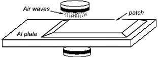 through-transmission C-scan arrangement
(see figure at right) in order to image defects and variations within a
sample consisting of a carbon-fiber composite patch on aluminum substrate. The transducers in this case were placed a
distance of ~10cm apart in a coaxial configuration, and with the normal of
the
sample parallel the transducer axes as shown. The source transducer was
excited into vibration using MicroAcoustic's
V-Pole™ and a ~400V
p-p toneburst voltage at frequency 1MHz. On the receive side, MicroAcoustic's
Q-Amp™
transimpedance preamplifier was employed.
through-transmission C-scan arrangement
(see figure at right) in order to image defects and variations within a
sample consisting of a carbon-fiber composite patch on aluminum substrate. The transducers in this case were placed a
distance of ~10cm apart in a coaxial configuration, and with the normal of
the
sample parallel the transducer axes as shown. The source transducer was
excited into vibration using MicroAcoustic's
V-Pole™ and a ~400V
p-p toneburst voltage at frequency 1MHz. On the receive side, MicroAcoustic's
Q-Amp™
transimpedance preamplifier was employed.
The sample:
The sample was manufactured at the
NRC
Institute for Aerospace Research as part of a research program
investigating the patching of CF-18
aluminum structures by composite materials.
The sample imaged here consisted of a 4-ply
carbon-fiber composite patch of ~1.75mm thickness which was bonded to an underlying
6.35mm
thick aluminum
plate. A portion of the aluminum plate substrate was left unpatched so as to provide a comparative region for
study. The edges of the patch had been carefully tapered during layup so as to provide smooth transitions from the bare aluminum
area to the thicker composite/aluminum area. Within the composite patch were 4
simulated delaminations, made by incorporating thin circular pieces of Teflon release sheet. Two of
the four Teflon defects were placed between the aluminum substrate and bonding layer while the other two were placed
between the second and third composite layers within the patch. Both sets of
Teflon defects were introduced in such a way that their existence was not
evident by visual inspection of the finished sample.
The resulting image:
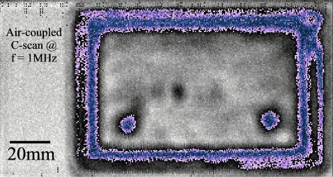
The resulting C-scan image above is typical of the excellent images that can be obtained by MicroAcoustic's BAT® transducers when investigating composite patches on aluminum without contact. Received signal amplitude is here mapped according to a modified grey scale image: highest levels are near white, lowest levels are near black, and the better part of the transition between high and low level is mapped to a blue-purple colour scale in order to better highlight the regions of low level through-transmission. Evident in the C-scan is the uniform transmission through the ~35mm wide aluminum area having no patch material (see left side of image). Uniform transmission occurs in this region since the aluminum plate itself contained no variations. The purple-blue rectangular edge of ~10mm width corresponds with the tapering region of the patch. The variations that appear within the tapering region (e.g., compare the uniform purple-blue top edge with the less-uniform other edges of the taper) shows that the taper and/or its bonding to the underlying aluminum was not entirely uniform around the patch. The central rectangular region of the patch at full thickness shows fairly uniform through-transmission. This indicates that the composite itself was manufactured and bonded fairly uniformly to the underlying aluminum (except of course for the two small circular regions of purple-blue at bottom-right and bottom-left which reveal the positions of the 2 simulated delaminations between the 2nd and 3rd plies of the patch). The other 2 delaminations are in the top-right and top-left corners within the tapered region, but their effects on thru-transmission levels are mostly masked by the effects of the taper.
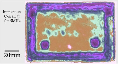
It is instructive to further compare the air-coupled image with a conventional immersion C-scan acquired by a 5MHz piezoelectric transducer operating in a pulse-echo mode (see image above). Note that the immersion scan occurred only over the patch-region and did not include measurements over the aluminum plate alone on left. By comparing this image with that taken by MicroAcoustic's BAT® transducers, it is readily apparent that the two scans have produced much the same result. In fact, the comparison leads to an observation that is more generally true: namely, provided a material can be practically scanned by air-coupled BAT® transducers, the images that result are generally comparable to immersion scans taken with conventional piezoelectric transducers at much higher frequencies of operation.
Conclusions:
1) This example shows that MicroAcoustic's BAT® transducers provide a practical non-contact alternative for the inspection and characterization of composite patches on underlying solid material substrates.
2) Delaminations, taper-uniformity, and uniformity of composite and bond-lines can all be easily detected and imaged in such structures using the MicroAcoustic's BAT®.
3) MicroAcoustic's BAT® transducers can provide similar C-scan images to piezoelectic immersion transducers operating at much higher frequencies.
4) Unlike other air-transducers available (which have much narrower frequency bandwidths), MicroAcoustic's BAT® transducers can be used with a wide variety of materials and material thickness without the need to change transducers. This saves time and money, since only one set of BAT® transducers are required for most of your inspection needs.
<< previous example ~ next example >>
*Note: The experimental results presented here were obtained by D.W. Schindel during his tenure at the NRC Institute for Aerospace Research. Contribution and reproduction of these results and figures occurs courtesy of the NRC Institute for Aerospace Research, Canada.
www.microacoustic.com