home
> products
> BAT's
> BAT
performance > typical signals
Typical ultrasonic signals in air using BATź transducers
impulse (or pulsed) response:
Because of
their broadband performance, BATź
transducers perform very well in ultrasonic systems involving impulsive (or pulsed) modes of operation. As a result, the MicroAcoustic
BATź
can be employed in a variety of applications using inexpensive pulser-receivers
or within laser-ultrasonic/air-coupled hybrid systems. Shown below right
is the typical 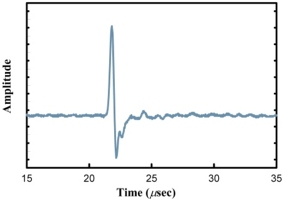 impulse response for a BATź
source transducer operating in air. The very narrow temporal response of <1”sec
is obviously well-damped and leads to accurate measurements based upon time of
flight. The waveform also shows an obvious
lack of "ringing" which leads to small dead-times for pulse-echo
operation and thus short stand-off distances between transducers and
objects of interest. Such excellent pulsed responses
are typical both of MicroAcoustic's
BATź sources and receivers. The source studied in this case
was MicroAcoustic's
unfocussed BAT-1
transducer having a 10mm diameter planar aperture, and the excitation
drive voltage used was obtained from a standard Panametrics
pulser-receiver (model 5052PR).
impulse response for a BATź
source transducer operating in air. The very narrow temporal response of <1”sec
is obviously well-damped and leads to accurate measurements based upon time of
flight. The waveform also shows an obvious
lack of "ringing" which leads to small dead-times for pulse-echo
operation and thus short stand-off distances between transducers and
objects of interest. Such excellent pulsed responses
are typical both of MicroAcoustic's
BATź sources and receivers. The source studied in this case
was MicroAcoustic's
unfocussed BAT-1
transducer having a 10mm diameter planar aperture, and the excitation
drive voltage used was obtained from a standard Panametrics
pulser-receiver (model 5052PR).
With such wideband performance, tonebursts are easily created and controlled in air using the MicroAcoustic BATź. This is demonstrated in the various signals below using two unfocussed BAT-1 transducers (one as source and one as receiver) which are set up to be facing each other at a distance of ~4cm between apertures. On the source side was employed the V-Pole polarization supply and on the receive side a Q-Amp preamplifier. The applied drive voltage in all cases had an amplitude of 5 Volts p-p and all receive signals are unaveraged. Application of a 30-cycle toneburst drive at a frequency of 400kHz and with no edge ramps yielded receive signal (a) below and its corresponding frequency content in the FFT alongside it at right.
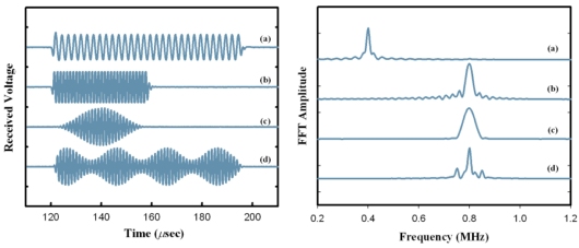
Notice the excellent transient response on the leading and trailing edges of signal (a), which exhibit no unwanted "ringing" that occurs with other narrow-band air-coupled transducers. By increasing the frequency upwards to 800kHz (though still at 30 cycle duration) leads to the second receive signal (b) and its associated frequency response curve beside. Here, the ripples in the frequency response curve around the main peak are due to the nice transient edges of the associated received toneburst signal. If you'd prefer to be free of these ripples in the frequency domain, then you can simply add a Hanning edge ramp filter of, say, 15-cycle length to the 800kHz drive signal and end up instead with receive signal (c) and its nicely smoothed frequency response curve. Or perhaps you're more interested in amplitude modulated waveforms in air, such as that shown in signal (d). This receive signal (d) resulted by partially modulating a 60-cycle toneburst drive at 800kHz with a sinusoid at 50kHz, and led to the appearance of the expected sidebands in the receive frequency response curve shown alongside. So, it is obvious from these signals that the transducers perform as you ask them to, which means you can get on with implementing whatever signal-processing schemes are of interest to you instead of spending time trying to correct for poor transducer responses.
The chirp response of MicroAcoustic's
BATź
transducers is also very well-behaved. To
demonstrate this, some typical chirp signals and their
corresponding frequency responses are shown below. These signals were
obtained using the same experimental setup described for the toneburst
signals above i.e., employing two facing
BAT-1 transducers with 5
Volts p-p drive amplitudes and no signal averaging. The first receive
signal on top (a) resulted from a linearly-swept chirp drive waveform from
400kHz to 800kHz over a 100”sec
duration and with no temporal edge ramp used to soften the edges. 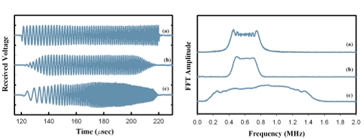
The fine transient behaviour of the BATź transducers is displayed here again, both by the lack of "ringing" on the leading and trailing edges of receive signal (a), and by the presence of the Fresnel ripple upon the otherwise flat-topped frequency response curve (a). (Fresnel ripple is a well-known characteristic in the frequency domain for any well-behaved chirp response with hard leading and trailing edges). Softening the chirp edges can be easily accomplished of course, by applying an edge filter to the drive chirp as shown by the second receive signal (b). In this case, a 20”sec wide Hanning filter was additionally employed on the drive chirp, and this can be seen to have reduced the Fresnel ripple in the associated frequency response curve (b). The chirp bandwidth can obviously be opened up much more than 400kHz with MicroAcoustic's BAT's, though the transfer functions of the transducers will start to colour the frequency response more and more. This is shown by the final example, receive signal (c), which resulted from a frequency swept chirp drive from 200kHz to 1500kHz over 100”sec duration and with a 5”sec edge ramp, and shows a very wideband though somewhat coloured response. Though all these examples have used a 100”sec chirp duration, any length of chirp can be applied to BATź transducers since there are no duty cycle limits with transducers of this kind. Such control over chirp responses, and such wideband chirp capabilities, makes possible real-time ultrasonic spectroscopy of materials in a non-contact mode, as well as allowing various advanced signal-processing techniques to be employed to advantage with MicroAcoustic BAT's .
www.microacoustic.com