home
> products
> BAT's
> BAT
examples
> example A.1.b
Air-coupled surface profilometry using a zone-plate focused BAT® transducer
The experiment:
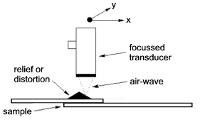
A BAT® transducer employing a micromachined zone-plate provides a well-focussed field that is well-suited to imaging the surfaces of materials. By aligning the focal point of the ultrasonic beam on a surface of interest, high resolution pulse-echo images can be obtained of the surface by mechanical scanning of the transducer or material surface. Surface relief of materials and/or distortions of surfaces away from some normal state can be measured in this way.
Because lateral resolution in such imaging work increases with decreasing focal diameter, a tightly focussed transducer field is required for successful surface imaging measurements. Shown below is the highly-focussed radiation profile of MicroAcoustic's zone-plate focussed BAT-2 transducer. This particular field pattern resulted from toneburst excitation of the transducer at a frequency of 700kHz..
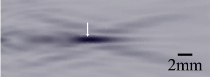
axial direction =>
The radiation pattern plots the highest intensity as black with the lowest intensities light grey. The ultrasonic beam is seen to emerge at left of the image and focus at a distance of ~ 10mm from the transducer (see white arrow). The beam waist or focal spot size at the position of the white arrow is less than 800µm across, which makes the device useful for high-resolution imaging in gases. The depth of field (or axial length of the focal region) is ~ 3mm.
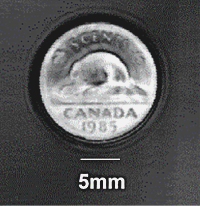
The overall resolution of a focussed air-coupled imaging system allows surprisingly high definition images of the surface relief of materials. This can be seen in the "ultrasonic photograph" taken at right for the front-side of a Canadian nickel coin. This image was acquired by plotting the pulse-echo amplitude obtained by a MicroAcoustic BAT-2 transducer as a function of transducer position as it scanned over the coin's surface. The image was acquired using toneburst excitation of the zone-plate at a frequency of 580kHz. Such an image has the equivalent lateral resolution to that which would be obtained by a focussed immersion transducer operating in water at a much higher frequency of 2.5MHz. The lateral resolution seen here can be improved ~3-fold by instead employing a zone-plate designed for 1.5MHz operation in air (see BAT-2 pages).
Measuring surface distortions:
Processes often occur in materials and structures that cause accompanying surface distortions, and such distortions can be imaged by focussed BAT® transducers for characterization purposes. This is demonstrated in the two air-coupled surfaces images below, both of which were obtained by the same zone-plate focussed BAT® in a simple pulse-echo configuration. The samples studied in this case were rivetted lap-joints from the aerospace industry. Lap-joints are of interest in this industry since they are used to form the skins of aircraft, where water-ingress and cyclic fatigue can in time lead to the buildup of corrosion product within the joint with subsequent surface pillowing and stress-corrosion cracking the result. The lap-joints studied here were processed identically to start, being formed from 2 overlapping layers of thin aluminum sheets. The overlapping sheets were rivetted together in each case in the overlap region using an array of 3 by 8 rivets. One sample was artificially corroded in a special corrosion chamber until sufficient corrosion product and pillowing resulted; the other sample was left in an uncorroded state for comparison. The sample that was corroded was further stressed within a cyclic fatigue jig until stress-corrosion cracking resulted within the joint.
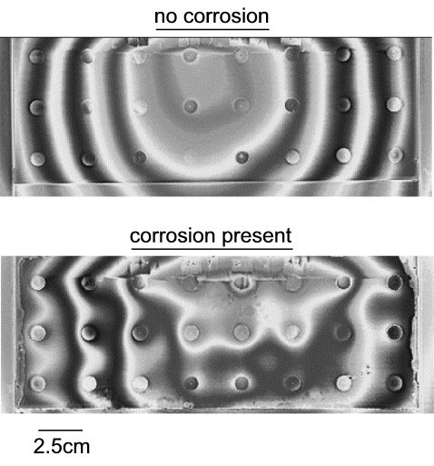
The fringes in the above air-coupled images are due to a special interference technique employed. The fringe lines are essentially just lines of equal distance from the transducer and because the method of producing the samples led to a slight bowing of the plates in the lateral direction, there is a background nominal fringe structure to both the corroded and uncorroded samples. The important thing to notice is the distortion of the nominal fringe line structure for the corroded sample. Such distortion of fringe lines was analyzed in detail and found to correlate well with the existence of corrosion product between the two layers of aluminum within the joint (as measured by independent NDT methods). This is of interest since it demonstrates that non-contact measurements of internal changes within materials can be studied with air-coupled transducers using measurements made only at the surfaces of the materials.
1) This example shows how suitably-focussed MicroAcoustic BAT® transducers provide an alternative non-contact technique for high-resolution imaging of the surfaces of materials.
2) The example further shows that processes that occur within materials (and structures) often create distortions at the surfaces of the materials which can be imaged for characterization purposes by non-contact air-coupled BAT® transducers.
3) Though an air-coupled ultrasonic surface imaging system cannot compete with its optical counterpart in terms of resolution, it does offer unique advantages over optical based systems, such as:
-
no sample illumination being required and so can operate equally well in complete darkness
-
often simpler to use and maintain, and typically less-expensive
-
no restrictions on sample surfaces i.e., samples can be optically opaque, transparent or reflective
-
a wide range of axial distances can be measured by a single system (i.e., from the micron level all the way up to centimeter levels and beyond)
<< previous example ~ next example >>
*Note: The experimental results presented here were obtained by D.W. Schindel during his tenure at the NRC Institute for Aerospace Research. Contribution and reproduction of these results and figures occurs courtesy of the NRC Institute for Aerospace Research, Canada.
www.microacoustic.com