home
> products
> BAT's
> BAT
examples
> example A.2.a
Tomographic imaging of flow-fields in gases using air-coupled BAT® transducers
The experiment:
This example shows how MicroAcoustic's
BAT® transducers can be used to non-invasively image flow fields in gases 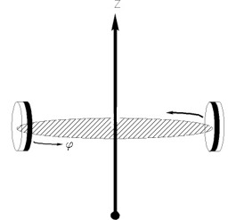 by
tomographic techniques. Two BAT-1
transducers are set up to be facing each other in a common plane at height
z, as shown in the figure at right. Pulsed ultrasonic
waves are launched by one transducer and received by the other while
moving and rotating the transducers about so as to fill the hash-marked
plane with a
large number of ultrasonic rays (i.e., like the spokes of a wheel). From
the received waveforms recorded for all ray-paths, tomographic
reconstruction algorithms are then used to reconstruct an image of the
ultrasonic properties of the gaseous medium within the plane (including
any variations that may be present therein). As variations can occur due
to the presence of pressure-, temperature- and flow- fields, for example,
or due to the presence of solid and liquid inclusions, ultrasonic images
of such variations can be obtained. The fact that the BAT®
sensors do not have to be inserted into the region of interest makes
the measurement non-invasive and so limits distortion of the flow-field
(or other variation) that you're trying to measure.
by
tomographic techniques. Two BAT-1
transducers are set up to be facing each other in a common plane at height
z, as shown in the figure at right. Pulsed ultrasonic
waves are launched by one transducer and received by the other while
moving and rotating the transducers about so as to fill the hash-marked
plane with a
large number of ultrasonic rays (i.e., like the spokes of a wheel). From
the received waveforms recorded for all ray-paths, tomographic
reconstruction algorithms are then used to reconstruct an image of the
ultrasonic properties of the gaseous medium within the plane (including
any variations that may be present therein). As variations can occur due
to the presence of pressure-, temperature- and flow- fields, for example,
or due to the presence of solid and liquid inclusions, ultrasonic images
of such variations can be obtained. The fact that the BAT®
sensors do not have to be inserted into the region of interest makes
the measurement non-invasive and so limits distortion of the flow-field
(or other variation) that you're trying to measure.
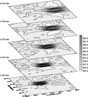 In
this example, the above experimental arrangement was used to obtain images
of a flow field created by a small gas-jet. In particular, air-coupled
ultrasonic tomographic images were obtained at 5 different heights above
the orifice of a small flow-nozzle, and the results are shown in the
figure at right for z = 20mm, 25mm, 30mm, 35mm and 40mm. The
variable used for tomographic reconstruction in these images was the
effective local ultrasound velocity within the tomographic planes. And, as
the local ultrasound velocity is affected by the local flow-velocity due
to the jets' flow, the images end up displaying a representation of the
flow field of the jet itself. Because the axis of the circular flow-jet
had been purposefully tilted away from vertical, the imaged cross-sections
of the jet appear elliptical. Also, the sizes of the ellipses can be seen
to increase with height due to expansion of the jet stream as it travels
upwards and away from the nozzle.
In
this example, the above experimental arrangement was used to obtain images
of a flow field created by a small gas-jet. In particular, air-coupled
ultrasonic tomographic images were obtained at 5 different heights above
the orifice of a small flow-nozzle, and the results are shown in the
figure at right for z = 20mm, 25mm, 30mm, 35mm and 40mm. The
variable used for tomographic reconstruction in these images was the
effective local ultrasound velocity within the tomographic planes. And, as
the local ultrasound velocity is affected by the local flow-velocity due
to the jets' flow, the images end up displaying a representation of the
flow field of the jet itself. Because the axis of the circular flow-jet
had been purposefully tilted away from vertical, the imaged cross-sections
of the jet appear elliptical. Also, the sizes of the ellipses can be seen
to increase with height due to expansion of the jet stream as it travels
upwards and away from the nozzle.
1) This example shows that MicroAcoustic BAT® transducers can be use for non-invasive imaging of flow fields in gases using tomographic reconstruction techniques.
2) Because BAT® transducers do not need to be placed within the flow field itself, images obtained in this way are not distorted by the presence of the sensors as occurs with other more-invasive flow-measurement techniques.
<< previous example ~ next example >>
www.microacoustic.com