home > products
> BAT's
>
BAT
examples
> example B.1.a
Air-coupled through-thickness C-scan of a thin CFRP plate using BATÛ transducers
The experiment:
The MicroAcoustic
BAT can be used to great effect for non-contact
Non-Destructive Testing (NDT) of
composite materials. In this example, two non-contact BAT-1
transducers were used in a  through-transmission C-scan arrangement
(see figure at right) in order to image defects and variations within a
thin carbon-fibre reinforced composite (CFRP) plate. The transducers in this case were placed a
distance of ~10cm apart in a coaxial configuration, and with the normal of
the plate parallel the transducer axes as shown. The source transducer was
excited into vibration using MicroAcoustic's
V-Pole and a ~400V
p-p toneburst voltage at frequency 685kHz. The toneburst frequency was
chosen so as to match to the nominal
through-thickness longitudinal resonance of the plate.
On the receive side, MicroAcoustic's
Q-Amp
transimpedance preamplifier was employed.
Because air-coupled inspection of composite materials is far more
practical than many people may know, it is important to mention that no signal processing or image processing
was required to obtain the results below.
through-transmission C-scan arrangement
(see figure at right) in order to image defects and variations within a
thin carbon-fibre reinforced composite (CFRP) plate. The transducers in this case were placed a
distance of ~10cm apart in a coaxial configuration, and with the normal of
the plate parallel the transducer axes as shown. The source transducer was
excited into vibration using MicroAcoustic's
V-Pole and a ~400V
p-p toneburst voltage at frequency 685kHz. The toneburst frequency was
chosen so as to match to the nominal
through-thickness longitudinal resonance of the plate.
On the receive side, MicroAcoustic's
Q-Amp
transimpedance preamplifier was employed.
Because air-coupled inspection of composite materials is far more
practical than many people may know, it is important to mention that no signal processing or image processing
was required to obtain the results below.
The sample:
The sample was a ~2mm thick, 16-ply quasi-isotropic CFRP plate with a
[0,+45,90,-45]2s fiber layup. Such a quasi-isotropic
layup places alternating layers of carbon fibers at 45¯ to one another
during manufacture. Within the sample were two carefully embedded defects:
the first was a 2.54cm square piece of 125çm thick Teflon tape, and the
second was a similarly sized brass shim. Such defects are often included in
composite test samples in order to simulate delaminations within the
material. In this case, the defects had been introduced in such a way as to
replace some of the central fibers, such that their existence was not
evident by visual inspection of the finished sample. Two impact damage sites
were also created in the finished panel by firing particles at high velocity
at the sample.
The resulting image:
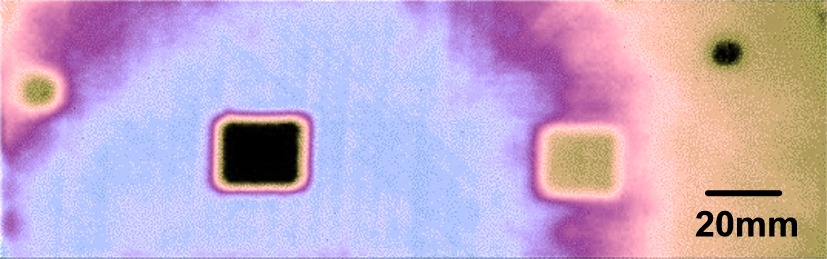
The resulting C-scan image above is typical of the excellent images that can be obtained by MicroAcoustic's BATÛ transducers when investigating composite materials without contact. Unaveraged receive signal amplitude is here mapped (highest to lowest) according to blue, purple, brown, and then black. The slowly varying background (blue through brown) is a result of subtle thickness variations not evident by visual observation of the sample. The black square at left is due to the simulated delamination created by the embedded Teflon tape, while the brown square at right reveals the position of the embedded brass shim. The two circular spots (far-left and far-right) are the impact damage sites. Just visible in the blue-white region (at 45¯ intervals) are the fiber-orientations within the layup; these usually appear in air-coupled C-scans despite ultrasonic wavelengths being much larger than characteristic fiber dimensions.
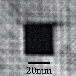 As
the above C-scan was acquired by an unfocussed BAT-1
transducer, the image resolution can be greatly improved by moving to the
use of a focussed BATÛ transducer. This is demonstrated in the
grey-scale image at right, which is a rescan of the region surrounding the
Teflon defect only for the same 16-ply CFRP plate. Not only are the
fiber-orientations now much more clearly resolved to show their
quasi-isotropic layup, but the ends of the fibers are just becoming visible
where they meet the square Teflon defect. Also, the cut line of the
fiber-fabric is now starting to show that it departed from being perfectly
square (see the right hand edge of the defect in particular where the fabric
bows inward slightly, and also note the missing ~2mm square of fabric in the
top-right corner). This is nothing short of impressive and especially so
since it is obtained by completely non-contact air-coupled means.
As
the above C-scan was acquired by an unfocussed BAT-1
transducer, the image resolution can be greatly improved by moving to the
use of a focussed BATÛ transducer. This is demonstrated in the
grey-scale image at right, which is a rescan of the region surrounding the
Teflon defect only for the same 16-ply CFRP plate. Not only are the
fiber-orientations now much more clearly resolved to show their
quasi-isotropic layup, but the ends of the fibers are just becoming visible
where they meet the square Teflon defect. Also, the cut line of the
fiber-fabric is now starting to show that it departed from being perfectly
square (see the right hand edge of the defect in particular where the fabric
bows inward slightly, and also note the missing ~2mm square of fabric in the
top-right corner). This is nothing short of impressive and especially so
since it is obtained by completely non-contact air-coupled means.
Conclusions:
1) This example shows that MicroAcoustic's BATÛ transducers provide a practical non-contact alternative for the inspection and characterization of composite materials.
2) Thickness variations, delaminations, inclusions, impact damage and fiber-orientation can all be easily detected and imaged in polymer-based composite materials using the MicroAcoustic's BATÛ.
3) Because of their wide bandwidths, BATÛ transducers allow tuning of toneburst drive frequencies to match nominal through-thickness resonances of samples. This greatly improves signal-to-noise ratios, and makes rapid air-coupled inspection of composite materials possible without signal averaging.
4) Unlike other air-transducers available (which have much narrower frequency bandwidths), MicroAcoustic's BATÛ transducers can be used with a wide variety of materials and material thickness without the need to change transducers. This saves time and money, since only one set of BAT transducers are required for most of your inspection needs.
<< previous example ~ next example >>
www.microacoustic.com