home
> products
> BAT's
> BAT
examples
> example B.1.b
Air-coupled through-thickness C-scan of a thick CFRP plate using BAT® transducers
The experiment:
MicroAcoustic
BAT™ transducers provide a practical non-contact alternative
for Non-Destructive Testing (NDT) of
composite materials. In this example, two non-contact BAT-1
transducers were used in a  through-transmission C-scan arrangement
(see figure at right) in order to image defects and variations within a
thick carbon-fibre reinforced composite (CFRP) plate. The transducers in this case were placed a
distance of ~10cm apart in a coaxial configuration, and with the normal of
the plate parallel the transducer axes as shown. The source transducer was
excited into vibration using MicroAcoustic's
V-Pole™ and a ~400V
p-p toneburst voltage at frequency 215kHz. The toneburst frequency was
chosen so as to match to the nominal
through-thickness longitudinal resonance of the plate.
On the receive side, MicroAcoustic's
Q-Amp™
transimpedance preamplifier was employed.
Because air-coupled inspection of composite materials is far more
practical than many people know, it is important to point out that no signal processing or image processing
was required to obtain the result below.
through-transmission C-scan arrangement
(see figure at right) in order to image defects and variations within a
thick carbon-fibre reinforced composite (CFRP) plate. The transducers in this case were placed a
distance of ~10cm apart in a coaxial configuration, and with the normal of
the plate parallel the transducer axes as shown. The source transducer was
excited into vibration using MicroAcoustic's
V-Pole™ and a ~400V
p-p toneburst voltage at frequency 215kHz. The toneburst frequency was
chosen so as to match to the nominal
through-thickness longitudinal resonance of the plate.
On the receive side, MicroAcoustic's
Q-Amp™
transimpedance preamplifier was employed.
Because air-coupled inspection of composite materials is far more
practical than many people know, it is important to point out that no signal processing or image processing
was required to obtain the result below.
The sample:
The sample was a 7mm thick, 50-ply CFRP plate having a [0,+90,0,-90] bidirectional
fiber layup. Such a bidirectional
layup places alternating layers of carbon fibers at 90° to one another
during manufacture. Within the sample was a string of carefully embedded
pieces of Teflon tape, which were included to simulate delaminations within the
material. Each of the Teflon tape defects had transverse dimensions of 1.3cm
by 1.3cm and a thickness of 37.5µm. These defects were introduced in such a way as to
replace some of the central fibers, and so their existence was not
evident by visual inspection of the finished sample.
The resulting image:
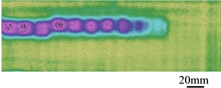
The resulting C-scan image above is typical of the excellent images that can be obtained by MicroAcoustic's BAT® transducers when investigating composite materials without contact. Unaveraged receive signal amplitude is here mapped (highest to lowest) according to light-green, blue, dark-purple, light-purple, and finally black. The string of small squares that appear are the simulated delaminations due to the pieces of Teflon tape. Just visible in the green region (at 90° intervals) are fiber-orientations, which usually appear in air-coupled C-scans.
Conclusions:
1) This example shows that MicroAcoustic's BAT® transducers provide a practical non-contact alternative for the inspection and characterization of composite materials.
2) Delaminations, inclusions, and fiber-orientation can all be easily detected and imaged in such composite materials using the MicroAcoustic's BAT®.
3) Because of their wide bandwidths, BAT® transducers allow tuning of toneburst drive frequencies to match nominal through-thickness resonances of samples. This greatly improves signal-to-noise ratios, and makes rapid air-coupled inspection of composite materials possible without signal averaging.
4) Unlike other air-transducers available (which have much narrower frequency bandwidths), MicroAcoustic's BAT® transducers can be used with a wide variety of materials and material thickness without the need to change transducers. This saves time and money, since only one set of BAT transducers are required for most of your inspection needs.
<< previous example ~ next example >>
*Note: The experimental results presented here were obtained by D.W. Schindel during his tenure at the NRC Institute for Aerospace Research. Contribution and reproduction of these results and figures occurs courtesy of the NRC Institute for Aerospace Research, Canada.
www.microacoustic.com