home
> products
> BAT's
> BAT
examples
> example B.2.a
Single-sided air-coupled C-scan of an aluminum lap-joint using BAT® transducers
The experiment:
MicroAcoustic
BAT transducers can be used for non-contact inspection of
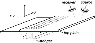
aluminum lap-joints given access to one side of the lap-joint only. This potential is demonstrated in the example below, where two non-contact BAT-1
transducers were used to inspect a bonded-rivetted aluminum lap-joint
sample in a single-sided pitch-catch C-scan  arrangement
(see figure at right). The source and receive transducers in this case
were inclined at an angle to the sample normal in
order to generate Lamb waves within the sample for inspection. The Lamb
waves, once generated, propagated through the
sample and reradiated leaky-waves back into the air for reception. The transducers in this case were placed
~10cm from the sample surface but were separated in the x-direction so as
to leave a path-length within the sample of ~3.5cm for Lamb wave propagation. The source transducer was
excited into vibration using MicroAcoustic's
V-Pole and a ~400V
p-p toneburst voltage at frequency 640kHz. On the receive side, MicroAcoustic's
Q-Amp
transimpedance preamplifier was employed.
The sample:
The sample was manufactured at the
NRC
Institute for Aerospace Research and consisted of two overlapping
aluminum plates of 1.15mm thickness which were bonded and rivetted together
in standard fashion and attached to an aluminum support stringer
as shown above using a central line of rivets. Each aluminum plate had dimensions
of approximately 200mm by 400mm and were overlapped by a distance of 70mm to
create a lap joint region having dimensions of 70mm by 400mm. Three lines of
rivets were used in total along the length of the lap joint with each line
consisting of 14 rivets each on approximately 1" centers. The sample
was painted after manufacture in a manner typical for such aerospace
structures.
The resulting image:

The resulting C-scan image above is typical of the images that can be obtained by MicroAcoustic's BAT® transducers when investigating aluminum lap-joints in a single-sided configuration. The image dimensions are 100mm by 400mm and correspond to a scan of the transducers overtop the lap-joint's top-plate only within the x-y plane. The top portion of the image containing the blue vertical lines is the lap-joint region itself while the grey area below is the single layer of aluminum on one side of the lap-joint. Receive signal amplitude is here mapped according to a modified grey scale image: highest levels are near white, lower levels are increasingly darker grey, and the lowest levels are mapped to a blue-purple colour scale in order to better highlight the regions of lowest receive signal levels. Evident in the C-scan is the uniform transmission through the ~30mm wide aluminum area beneath the lap-joint (bottom of image). Uniform signal level occurs in this region since the aluminum plate itself contained no significant variation. Reduced receive signal occurs in between the rivets within the lap-joint region (see dark grey areas) since Lamb waves propagating within the top plate leak energy through the bond-line into the bottom aluminum plate below, thereby reducing the amount of energy that can be received by the receive transducer. One square region of the bond-line in the center of the scan shows up as light grey however (and on par with levels received in the aluminum only area on bottom) indicating a disbonded and/or poorly-bonded area of the lap-joint. Note that the rivets show up as vertical blue lines in the image due to the finite propagation length of Lamb waves in the plate which results in a short-range spatial integration in the vertical (or x) direction.
Conclusions:
1) This example shows that MicroAcoustic's BAT® transducers can be used for same-sided non-contact inspection of bonded, rivetted aluminum lap-joints of interest to the aerospace industry.
2) Delaminations and uniformity of bond-lines can be detected and imaged in such structures using the MicroAcoustic BAT®.
3) Unlike other air-transducers available (which have much narrower frequency bandwidths), MicroAcoustic's BAT® transducers can be used with a wide variety of materials and material thickness without the need to change transducers. This saves time and money, since only one set of BAT transducers are required for most inspection needs.
<< previous example ~ next example >>
*Note: The experimental results presented here were obtained by D.W. Schindel during his tenure at the NRC Institute for Aerospace Research. Contribution and reproduction of these results and figures occurs courtesy of the NRC Institute for Aerospace Research, Canada.