home
> products
> BAT's
> BAT
examples
> example
B.1.g
Air-coupled through-thickness C-scan of Nomex/CFRP composite panel using BATÛ transducers
The experiment:
MicroAcoustic
BAT transducers provide a practical non-contact alternative
for Non-Destructive Testing (NDT) of
composite materials. In this example, two non-contact BAT-1
transducers were used in a  through-transmission C-scan arrangement
(see figure at right) in order to image defects and variations within a multi-layer
sample consisting of a Nomex honeycomb core with CFRP faceplates. The transducers in this case were placed a
distance of ~10cm apart in a coaxial configuration, and with the normal of
the plate parallel the transducer axes as shown. The source transducer was
excited into vibration using MicroAcoustic's
V-Pole and a ~400V
p-p toneburst voltage at frequency 609kHz. On the receive side, MicroAcoustic's
Q-Amp
transimpedance preamplifier was employed.
Because air-coupled inspection of composite materials is far more
practical than many people may know, it is important to point out that no signal processing or image processing
was required to obtain the result below.
through-transmission C-scan arrangement
(see figure at right) in order to image defects and variations within a multi-layer
sample consisting of a Nomex honeycomb core with CFRP faceplates. The transducers in this case were placed a
distance of ~10cm apart in a coaxial configuration, and with the normal of
the plate parallel the transducer axes as shown. The source transducer was
excited into vibration using MicroAcoustic's
V-Pole and a ~400V
p-p toneburst voltage at frequency 609kHz. On the receive side, MicroAcoustic's
Q-Amp
transimpedance preamplifier was employed.
Because air-coupled inspection of composite materials is far more
practical than many people may know, it is important to point out that no signal processing or image processing
was required to obtain the result below.
The sample:
The sample consisted of a 9mm
thick Nomex honeycomb core which was bonded and sandwiched between two 1mm
thick carbon-fibre reinforced polymer (CFRP) faceplates. In order to provide
defects within the sample, four regions of the interface
between faceplate and Nomex core were left adhesive free during manufacture. These defects were
not evident by visual inspection of the finished sample.
The resulting image:
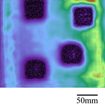
The resulting C-scan image above is typical of the excellent images that can be obtained by MicroAcoustic's BATÛ transducers when investigating composite materials without contact. Receive signal amplitude is here mapped (highest to lowest) according to orange, yellow, green, light blue, purple and finally black. The four black square regions that appear reveal the positions where no bond was applied between the faceplate and Nomex core. The more gradual colour variations of the background (from purple-blue in the middle to orange-yellow at the right edge) are due to thickness variations not evident from visual inspection of the panel.
Conclusions:
1) This example shows that MicroAcoustic's BATÛ transducers provide a practical non-contact alternative for the inspection and characterization of multi-layer composite materials employing honeycomb cores.
2) Delaminations, disbonds, and thickness variations can all be easily detected and imaged in such composite materials using the MicroAcoustic's BATÛ.
3) Unlike other air-transducers available (which have much narrower frequency bandwidths), MicroAcoustic's BATÛ transducers can be used with a wide variety of materials and material thickness without the need to change transducers. This saves time and money, since only one set of BAT transducers are required for most of your inspection needs.
<< previous example ~ next example >>
*Note: The experimental results presented here were obtained by D.W. Schindel during his tenure at the NRC Institute for Aerospace Research. Contribution and reproduction of these results and figures occurs courtesy of the NRC Institute for Aerospace Research, Canada.
www.microacoustic.com