home
> products
> BAT's
> BAT
examples
> example B.1.c
Air-coupled inspection of bond-line thickness in aluminum lap-joints using BAT® transducers
The experiment:
MicroAcoustic
BAT™ transducers have proven capable of making many important
non-contact measurements of bonded multi-layer structures, including
bonded aluminum lap-joints of great interest in the aerospace
industry. In this example, two non-contact BAT-1
transducers were used in a normal-incidence through-transmission C-scan arrangement
in order to image and characterize variations in the bond-line of a
carefully prepared aluminum lap-joint sample. The transducers in this case were placed a
distance of ~10cm apart in a coaxial configuration, and with the normal of
the lap-joint sample parallel to the transducer axes. The source transducer was
excited into vibration by a ~400V
p-p toneburst voltage, whose frequency was altered from scan to scan so as
to produce a series of C-scans at different toneburst frequencies. The toneburst
frequencies selected were
chosen to lie in a range that matched to a certain type of longitudinal
"mass-spring" resonance within the lap-joint structure.
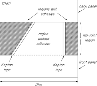 The lap-joint sample was manufactured by the Institute
for Aerospace Research (IAR) at Canada's National
Research Council using two identical 1.58mm thick aluminum panels. The
front panel was made to overlap the back panel by more than 50% of their
surface areas in order to form the lap-joint region shown in the figure at
right. FM73 Cyanimid film adhesive (of nominal thickness 150µm)
was employed in the lap-joint region to bond the panels, though a large
trapezoidal region in the center was purposefully left without adhesive to
create a perfectly disbonded region. In order to limit the spread of
adhesive into the disbond region during subsequent processing in an
autoclave, Kapton tape dams were employed as shown along the bond/no-bond
lines. Best efforts were made by those with much expertise at IAR in
creating such samples to keep the adhesive layer thickness as uniform as
possible. But even with such care and experience, thickness variations of
the bond line were still present after manufacture (a fact that is rather
telling of the likely state of bond-line uniformity in actual lap-joints
of aircraft and other engineering structures).
The lap-joint sample was manufactured by the Institute
for Aerospace Research (IAR) at Canada's National
Research Council using two identical 1.58mm thick aluminum panels. The
front panel was made to overlap the back panel by more than 50% of their
surface areas in order to form the lap-joint region shown in the figure at
right. FM73 Cyanimid film adhesive (of nominal thickness 150µm)
was employed in the lap-joint region to bond the panels, though a large
trapezoidal region in the center was purposefully left without adhesive to
create a perfectly disbonded region. In order to limit the spread of
adhesive into the disbond region during subsequent processing in an
autoclave, Kapton tape dams were employed as shown along the bond/no-bond
lines. Best efforts were made by those with much expertise at IAR in
creating such samples to keep the adhesive layer thickness as uniform as
possible. But even with such care and experience, thickness variations of
the bond line were still present after manufacture (a fact that is rather
telling of the likely state of bond-line uniformity in actual lap-joints
of aircraft and other engineering structures).
The resulting images:
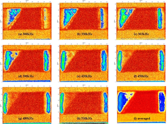
The resulting C-scan images above
are typical of the excellent results that can be obtained by MicroAcoustic's
BAT® transducers when investigating bonded aluminum
lap-joint structures without contact. Except for image-i at
bottom-right, these
images were obtained by exciting the BAT®
source transducer at different toneburst
frequencies ... starting at 300kHz in image-a (top-left) and
increasing in 30kHz
increments in a left-to-right/top-down order through to 510kHz in image-h
(bottom-middle). Image-i is not a C-scan but a pixel-by-pixel average
of all the other C-scans. The dark-orange trapezoidal area in the
center of each image indicates the area of lowest through-transmission, and
corresponds with the region of the sample that contained no adhesive
whatsoever (i.e., the simulated perfect disbond). The light-orange regions on
top and bottom of the images are the regions on either side of the
lap-splice where only one layer of aluminum was present. To the right and
left of the central disbond are the regions containing adhesive of varying
thickness. Here, dramatic increases in through-transmission
(blue-green-grey) occurs wherever the applied toneburst frequency matches
the longitudinal resonance mode of the Al/bond/Al structure. The regions of
high-transmission nearest the central disbond at low frequency are seen to
shift toward the outer edges of the sample as the frequency increases. This
occurs because the bond-line thickness is greater nearest the central
disbond and thinner toward the edges. Theoretical modelling of the resonance
of the Al/bond/Al structure allowed bond-line thickness in the
high-transmission areas to be estimated from the C-scan images: 360µm,
300µm, 245µm,
210µm, 185µm,
160µm, 140µm
and 125µm
for images a through h respectively. The fact that these
measurements of bond thickness agreed with independent measurements by a
machinists contacting micrometer are impressive. The pixel-by-pixel average
of all C-scans (image-i) is of interest since it proves that all
areas in which adhesive were present were well-bonded despite thickness
variations being present. Image-i also provides a warning to users of
narrow-bandwidth air-coupled transducers, for such a transducer operating at
a center frequency of 510kHz, say, could only have produced an image like
image-h and thereby led the user to the incorrectly conclude that
only the outer-most edges of the adhesive regions were well-bonded.
Conclusions:
1) This example shows that MicroAcoustic's BAT® transducers provide a practical non-contact alternative for the inspection and characterization of bond-lines in multi-layer structures such as bonded aluminum lap-joints. This is a relatively important result for the aerospace industry, partly because bond-line thickness is thought to affect strength and fatigue-life of lap-joints that form the skins of aircraft, but also because non-contact inspection methods are required in this industry for practical and economic reasons.
2) Because of their wide
bandwidths, BAT®
transducers allow tuning of toneburst drive frequencies to match nominal
through-thickness resonances of bonded lap-joints. This in turn avoids the
incorrect and costly conclusions that would otherwise result from the use
of narrow-bandwidth air-transducers as to the local state of bonding or
disbonding within the lap-joint.
<< previous example ~ next example >>